
Non-Invasive Energy Monitor with PZEM and ESPHome
This post has been sponsored by donations from users who visit it. Special mention to @cantavro for his contribution to pay for the materials. You can support me through Paypal, GitHub or simply by disabling the ad blocker.
With the price of electricity at historical highs, and the forecast of its continuous increase, we believe that it is necessary to have a way of measuring electricity consumption and the parts of the house with the highest energy consumption in order to optimize its use, and, in this way reduce our bill. A simple way to achieve this goal is by installing energy meters per device and/or globally throughout the home. In this article we are going to focus on placing a energy meter in the electrical panel to measure the consumption of our entire house.
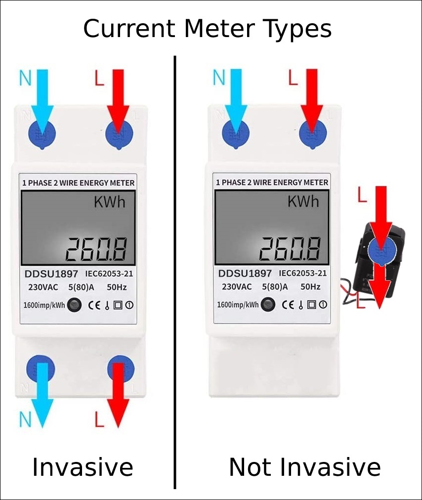
There are many devices on the market that fulfill this task. But from this blog we have preferred to make our own for very little money and that is also not invasive, that is, it does not require that the line with the current to be measured passes through the device, therefore, its assembly and use is safer.
WARNING: This is an advanced tutorial and requires touching the electrical panel of the house, that implies certain knowledge of electricity and electronics, as well as ensuring the total cut of the current before handling.
Materials
- An ESP8266 or ESP32 module that we will use to obtain the meter data and transmit it over Wi-Fi to our server. You can find different models on AliExpress.
- PZEM-004T V3 meter that you can buy on AliExpress. Version 1 is also valid, but it offers less data.
- A current clamp / ring CT. Normally included with the meter, it must withstand at least the limit intensity that the line that we are going to measure to withstand. You can choose whether to use a clamp, which, although it does not require disconnection of the cable we want to measure, gives us less precise data, or a ring, which has more precision, but requires that we first pass the cable, which will have to be disassembled .
- Dupont cables to connect both devices. Although the ideal is to make a circuit you can use dupont cables and a development board to do the tutorial.
- A transformer from 220V to 5V as a mobile charger or a more suitable transformer that we can find again on AliExpress.
- Blue and Brown cables to connect the PZEM-004T meter to the current.
Software
First we are going to put the software generated with ESPHome to the ESP module. If you are not familiar with ESPHome, I recommend you read this article and go through its documentation here.
The following code is just a template that can be adapted to the needs of each one:
# Remember to change the platform and board as appropiate to your ESP module.
# https://esphome.io/components/esphome.html
# ESP8266: https://esphome.io/devices/nodemcu_esp8266.html
# ESP32: https://esphome.io/devices/nodemcu_esp32.html
esphome:
  name: "energy-meter-pzem004t"
  platform: ESP32
  board: nodemcu-32s

# Wi-Fi configuration to which the module will connect
# https://esphome.io/components/wifi.html
wifi:
  ssid: <WIFI_NETWORK_NAME>
  password: <WIFI_NETWORK_PASSWORD>
  manual_ip:
    static_ip: <DEVICE_STATIC_IP>
    subnet: <NETWORK_SUBNET>
    gateway: <NETWORK_GATEWAY>

# API so that Home Assistant can connect to the module
# https://esphome.io/components/api.html
api:

# Web server to be able to consult information with a Web browser
# https://esphome.io/components/web_server.html
web_server:

# OTA component to be able to update the module without the need for cables
# https://esphome.io/components/ota.html
ota:

# Logger to record the messages sent by the device and be able to debug
# https://esphome.io/components/logger.html
logger:

# We indicate the pins where we have connected TX and RX of the device, taking into account that TX-> RX, RX-> TX must always be inverted
uart:
  rx_pin: GPIO16
  tx_pin: GPIO17
  baud_rate: 9600
  # stop_bits is only necessary if indicated by the log while testing the circuit
  #stop_bits: 2

sensor:
  # We will use pzemac or pzem004t depending on whether we are using a PZEM-004T V3 or V1
  - platform: pzemac
    current:
      name: "Current"
    voltage:
      name: "Voltage"
    energy:
      name: "Energy"
    power:
      name: "Power"
    frequency:
      name: "Frequency"
    power_factor:
      name: "Power Factor"
    update_interval: 30s

# We indicate the pin of the board's LED to blink according to its status
# https://esphome.io/components/status_led.html
status_led:
  pin: GPIO2
We can now generate the compiled binary from the .yaml file and put it in the ESP module. As always, it can be done by USB or if we already have it previously configured by OTA. Once ready we can go to the circuit.
Connections
We are going to follow a fairly simple scheme that can be adapted to different needs and assemblies. For now, and for testing…
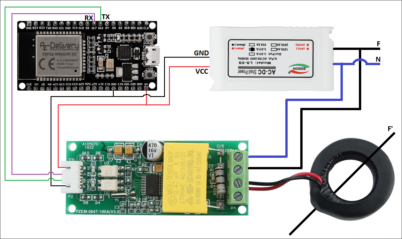
| NodeMCU ESP32S | PZEM004-T V3 | Transformer | Ring |
|---|---|---|---|
| 5V | 5V | Red/+/VCC/5V | |
| GND | GND | Black/-/GND | |
| GPIO16 | TX | ||
| GPIO17 | RX | ||
| CT (Any) | Black | ||
| CT (Any) | Red | ||
| Phase | Phase | ||
| Neutral | Neutral |
Phase and Neutral wires will be connected to direct current from the house.
Through the interior of the ring we will have to pass the Phase cable (Black) on which we want to make the measurements, and it may or may not be the same as the one we have used to give current to the circuit.
Note: Some ESP modules allow 5V current output per pin, others do not. If you are going to power the ESP module with a USB cable and feed the PZEM-004T module from its 5V/VCC and GND pins, check that these pins offer the desired current.
The idea is to carry out tests on this scheme and then carry out a more adequate and safe assembly and installation, since we remember that it will go inside the electrical panel.
Since the ESP module really works at 3.3V and if you want to power the PZEM-004T module with this voltage, it is recommended to place a 1K resistor between 5V and RX of the PZEM-004T itself. The Tasmota website has a lot of information about this behaviour.
Testing
Once the software is configured and the circuit is connected, we can plug in the transformer, we wait a few seconds and we can access the Web Server by typing the IP of the device in any Web browser.+
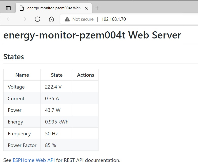
If we have made the connections well and the line that we are measuring is currently consuming, we will see how the values shown change.
Our energy meter would be ready!
Conclusion
By improving the circuit and protecting it, we can mount the energy meter that we have just built in our electrical panel and control consumption and other parameters that provide data on how our electrical installation behaves. With this, optimize expenses and detect possible phantom consumption.
If we have space in the frame, we can buy boxes with support for din rail (in AliExpress there are several models) and place the components inside.
This and other articles complement the documentation of the GitHub repository where all the configuration of my ESP8266/ESP32 devices with ESPHome are available.